Object 13 "Surface" (Entity Type "Object") Changed in Version 2021.0
|
|
Object 13 "Surface" (Entity Type "Object") Changed in Version 2021.0 |
www.CAD6.com |
|
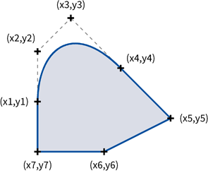
A surface is in fact a list of several surfaces. Each surface starts with a start-point followed by a sequence of curve elements. Three types of curve elements are available:
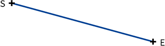
Line
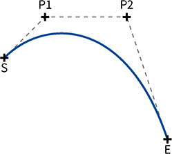
Bézier curve
Point = (1-t)³ × Start + 3t(1-t)² × Pivot1 + 3t²(1-t) × Pivot2 + t³ × End (0<=t<=1)
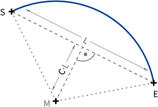
Circular arc
Center.x = 0.5 * ( Start.x + End.x ) - Curvature * ( End.y - Start.y ) Center.y = 0.5 * ( Start.y + End.y ) + Curvature * ( End.x - Start.x )
Each surface is automatically closed, i.e. its start-point and end-point are connected with a line. When creating a surface, you should not end each surface with a final point identical to its start point (although you may).
If a surface consists of only one curve, simply the inside area of that curve will be filled:
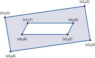
If a surface consists of multiple curves they will be filled alternately, i.e. only areas overlapped by an odd number of curve's insides will be filled. If, e.g., a small curve lies inside a large one, this small curve will be transparent, as its inside in overlapped by two curves (even number!):
If a surface is drawn with a non-solid line type, this line type has to be continued along the complete surface. A surface may contain up to 10,000 nested surfaces made of up to MKI_MaxEntityPoints data blocks in total.
Data Block SequenceData Block 001( Start )
LineData Block 002( End )
Bézier curveData Block 007( Pivot1 ) Data Block 008( Pivot2 ) Data Block 002( End )
Circular arcData Block 009( Arc ) Data Block 102( Orientation, Curvature )
ParametersStart [MKI_POINT] Start point of one curve. Pivot1 [MKI_POINT] First pivot point of a Bézier curve. Pivot2 [MKI_POINT] Second pivot point of a Bézier curve. End [MKI_POINT] End point of a line or a Bézier curve. Arc [MKI_POINT] End point of a circular arc. Orientation [double] Direction of the arc. If Orientation >= 0, the arc is drawn counter-clockwise from the start angle to the end angle. If Orientation < 0, the arc is drawn clockwise. Curvature [double] Indirect definition of the arc's radius, see section "Circular Arc" above. Valid range: -1e100 ≤ x ≤ 1e100.
Attributes New in Version 2021.0A surface may contain attribute data blocks (see MKI_BLOCK_ATTRIBUTE) of types "local", "outline", and "point". Their position in the list of data blocks is as follows:
The total number of attributes of each type (local, outline, point) per respective element (entity, outline, and point) is limited to MKI_ATTRIBS_PER_OBJECT.Interface Command SequenceMKI_ObjectOpen, Type = MKI_OBJ_SURFACE MKI_ObjectAddPoint, Type = MKI_DB_POINT_START ... MKI_ObjectAddPoint, Type = MKI_DB_POINT_END ... MKI_ObjectAddPoint, Type = MKI_DB_POINT_PIVOT1 MKI_ObjectAddPoint, Type = MKI_DB_POINT_PIVOT2 MKI_ObjectAddPoint, Type = MKI_DB_POINT_END ... MKI_ObjectAddPoint, Type = MKI_DB_POINT_ARC ...
|
CAD6interface 2026.1 - Copyright 2026 Malz++Kassner® GmbH