|
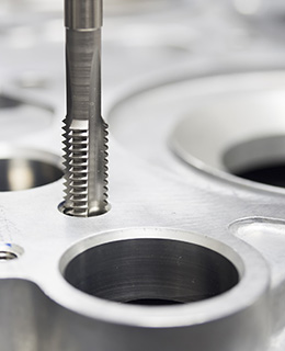
The CAM part supports the following machining procedures: milling, turning, water jet cutting, laser cutting, cutting, plotting, and positioning. It offers a variety of functions to create drawings which are to be exported to a CNC machine.
Commands like milling cutter compensation, insert rib, milling order control, milling time calculation and a graphical 3D preview let you create drawings that are directly milled later. Extensive tool and machine settings, plus output of custom commands using blocks with a script language, give you the complete control over what the post-processors finally output to the machine.
The universal post-processor creates the actual milling data by using the geometric data and the associated machine information of the drawing. This data is transferred directly to the control program of a machine. Due to the fact that there are machine specific differences when interpreting the milling data, the post-processor is equipped with adjustable options and configurable by scripts for individual use.
|